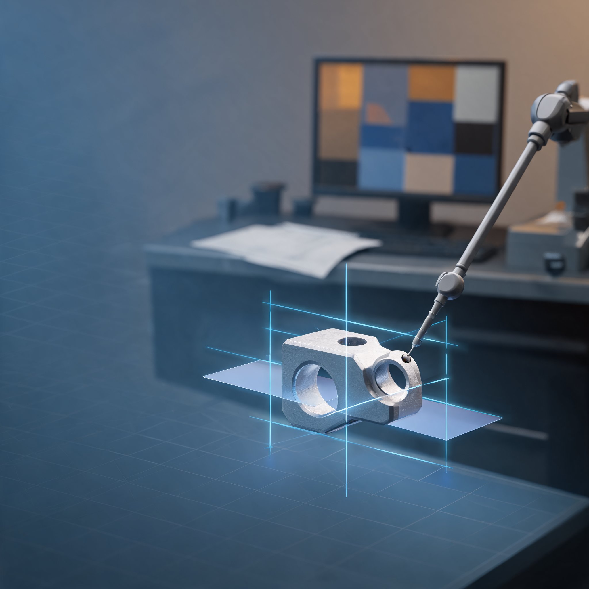
Geometric Dimensioning and Tolerancing (GD&T) is the shared vocabulary through which design, manufacturing and inspection teams describe what a part must do. Used correctly, it helps ensure a part assembles and functions as intended; misread, it produces conflicting measurements, scrap and repeated exchanges between departments. Metrologic DCS, which supplies metrology software, has set out four recommendations for making that chain more reliable, from reading the design intent to the documents delivered to the shop floor. The company notes that the risk of error keeps growing as Product Manufacturing Information (PMI) is embedded in more CAD files and as standards continue to evolve.
Start from the PMI
Using PMI means first decoding the design intent: which feature is targeted, which references apply and which tolerance is specified. Metrologic DCS argues that doing this by hand is error-prone, because a value keyed in incorrectly or a misunderstood reference can lead a part to be inspected against a requirement that was never specified. Its advice is to use software that takes the PMI as its starting point instead of asking the programmer to re-enter tolerances, so that features and their evaluations are generated from the part's digital definition. The stated result is no re-keying, fewer interpretation gaps and time saved from the first step of program preparation.
Do not rebuild datum reference frames by hand
The Datum Reference Frame (DRF) establishes where measurement starts. It consists of reference features, typically labelled A, B and C, and determines which degrees of freedom of the part are constrained during evaluation. According to the company, building the frame in the wrong order, or selecting the degrees of freedom poorly, can allow the same part to be declared conforming or non-conforming depending on which operator is at the machine — which it describes as a major source of GD&T misinterpretation. The recommendation is to automate the step so that the DRF and the constrained degrees of freedom follow the drawing definition rather than an operator's judgement, making results repeatable across operators, machines and sites. In the company's Metrolog software, the DRF is created automatically when a GD&T is evaluated and the degrees of freedom are selected accordingly.
Reuse the DRFs already defined in the model
Reference features are already defined in the CAD model, with labels A, B and C placed by the design office. Recreating them during program preparation wastes time, invites discrepancies and forces rework whenever the definition changes, Metrologic DCS says. On a part carrying many annotations, it can also be difficult to track which ones have been handled and which still need measuring. The suggested approach is to start from the DRFs carried in the PMI and predefine GD&T from them, while keeping a clear view of where each annotation sits on the part and where its measurement stands. Metrolog's Scan GDT function reads the decoded PMI and assigns a status, so both the decoding and the measurement can be validated.
Match the report to its reader
A report that shows only pass or fail does not tell the shop floor what to correct. If an operator cannot identify the type of defect in front of them, the company says, adjustment becomes trial and error, generating scrap and repeated correction loops. Its guidance is to tailor reporting: a table of numerical values for quality control, a Go/No-Go sheet for a quick decision, and a decomposition analysis for the operator. Metrolog separates the defect of an evaluated feature into four independent types — form, size, position and orientation — alongside the overall defect, so the dominant type, and therefore the first thing to correct, is immediately visible. Metrologic DCS presents this as a way to reduce scrap and shorten corrective action.